1902 Encyclopedia > Railway, Railways (Railroad) > Railway Construction: Bridges and Viaducts. Forth Bridge.
Railway, Railways
(Part 14)
C. RAILWAY CONSTRUCTION (cont.)
Railway Construction: Bridges and Viaducts. Forth Bridge.
Bridges
There are very few level crossings on English railways—that is, the crossing of one railway with another, or with a common road, at the same level—the chances of accidents having demanded, in general, the construction of bridges over or under the railway. The general appearance of an ordinary stone or brick bridge is represented by fig. 19, showing in elevation a bridge over or under the railway.
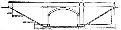
Fig. 19. Ordinary bridge over or under a railway. The left-hand side is for a cutting, and a bridge over the railway; the right-hand side is for an embankment and a bridge under the railway; the difference is in the foundations.
The minimum height of a bridge over the railway is ruled by the elevation necessary to clear the top of the chimney of the locomotive. An excellent method of carrying roads over railways where the height is limited and the span is moderate, consists in erecting flat-arched cast-iron beams over the railway, and throwing brick aches of small span between the beams upon their lower flanges, to carry the roadway. Thus the vertical depth from the soffit or crown of the main arch to the roadway above may but very little exceed the depth of the beam, which is apparent in the sectional view. This method of construction is moreover, well adapted for skew-bridges. Cast-iron has, however, as material for railway structures, been very generally superseded by wrought-iron, forming plate girder bridges. Timber is now almost unheard of for railway bridges on account of its want of durability and stiffness; and such bridges as have formerly been built of timber in Great Britain are being rebuilt of stone, brick, or plate-iron.
Viaducts
The longest viaduct in England is perhaps the Congleton, on the Manchester and Birmingham Railway; it is of stone, 1026 yards or more than half a mile in length and 106 feet high, and it cost £113,000, or £113 per yard run. The Dane viaduct, on the same line, is of brick, 572 yards long and 88 feet high, and it cost £54,000, or £96 per yard run, having 23 arches of 63 feet span. The Avon viaduct, on the Midland Railway, is of brick, 240 yards in length and 51 feet high, with 11 arches of 50 feet span; it cost £14,000, or £60 per yard run. For comparison it may be stated that the Britannia Tubular Bridge across the Menai Straits, 616 yards long and 104 feet high, cost £600,000, or £974 per yard run. On the different lines entering London there are several miles of brick viaducts in the approaches to termini, and also at Manchester and other large cities and towns. Many interesting details might be given as to bridges and viaducts of the larger kind, but we must here confine ourselves to some account of the Forth Bridge, now in course of construction at Queensferry, referring the reader for other examples to the article BRIDGES.
Forth Bridge
The Forth Bridge, designed by Mr. John Fowler and Mr. Benjamin Baker, is the largest and most remarkable railway bridge in the world. One of its spans is shown in elevation and plan in fig. 20.
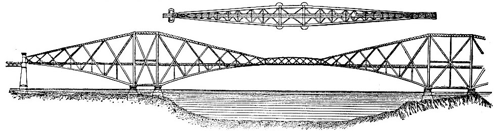
Fig. 20. The Forth Bridge.
The bridge consists of 2 spans of 1700 feet each, 2 of 675 each, 15 of 168 each, and 5 of 25 each. Including the width of the piers, there is almost exactly 1 mile of main spans and half a mile of approaches by viaducts, making together about 1 1/2 miles of total length. The clear headway under the centre of the bridge is 150 feet above the level of high water, and the highest part of the bridge is 361 above the same level. Each of the three main piers consists of a group of four cylindrical piers of masonry and concrete, 49 feet in diameter at the top and from 60 to 70 in diameter at the bottom. The deepest pier is about 70 feet below low water, and the rise of the tide is 18 feet at ordinary spring tides. In the piers there are about 120,000 cubic yards of masonry and in the superstructure 44,500 tons of steel. The contract was let for the sum of £1,600,000, being at the rate of £645 per lineal yard. An impression of the magnitude of the bridge is derived from a comparison with the largest railway bridge in England, the Britannia Bridge, which has a span of 465 feet, the ratio of which to that of the Forth Bridge—1700—is as 1 to 3.65. The site of the Forth Bridge is at Queensferry. At this place the Firth of Forth is divided by the island of Inchgarvie into two channels, which, being as much as 200 feet in depth, precluded the construction of intermediate piers. Hence the adoption of two large spans of 1700 feet each, between which the central pier is founded on the island midway across. The bridge is composed of three double lattice-work cantilevers, like scale-beams, 1360 feet in length, poised on three substructures, and connected at their extremities by ordinary girders 350 feet long, which complete the main spans. The bridge is taper in plan, varying from a width of 120 feet—the distance apart of the lower members of the cantilevers at piers—to a minimum of 31 1/2 at the ends, in order to confer a degree of stiffness laterally, for resisting irregular stresses, wind-pressure in particular. The columns above the piers, forming the bases of the cantilevers, are 12 feet in diameter. The lower booms, as well as the struts of the cantilevers, being the members in compression, are circular in cross section, this form of section having been selected as the most effective for resisting compressive stress. The lower boom is at the piers 12 feet in diameter, constructed of plates 1 1/4 inches in thickness. The size is gradually reduced towards the ends, where the diameter is 5 feet, made of plates three-eights of an inch in thickness. Correspondingly the upper member of each cantilever is a tapering box-lattice girder, rectangular in section, 12 feet deep by 10 wide at the piers, and 5 feet by 3 at the ends. The central girders are 32 feet apart. The wind-pressure is assumed for calculation at a maximum of 56 lb per superficial foot. It is calculated that the maximum possible stress on member of the bridge is at the rate of 7 1/2 tons per square inch of section. The required ultimate strength of steel under compression is from 34 to 37 tons per square inch, and under tension from 30 to 33 tons. Between the two main girders the double line of way is to be carried on an interval viaduct (see smaller figure in fig. 20), supported by trestles and cross girders. The way will consist of heavy bridge rails, Brunel section, laid on longitudinal sleepers bedded in four steel troughs, into which the wheels will drop in case of derailment, and then run on the sleepers.
Read the rest of this article:
Railway, Railways - Table of Contents
|