1902 Encyclopedia > Railway, Railways (Railroad) > Permanent Way: Rails; Kinds of Rails; Chairs; Keys; Fish Plates; Sleepers; Double-Headed Rails; Bull-Headed Rails; Flange Rails.
Railway, Railways
(Part 27)
E. PERMANENT WAY (cont.)
Rails; Kinds of Rails; Chairs; Keys; Fish Plates; Sleepers; Double-Headed Rails; Bull-Headed Rails; Flange Rails
Rails
"The experience of the last twenty-five years," said Mr. George Parker Bidder, speaking in 1861, "has shown that one system has been adopted almost universally—the double-headed rails, upon chairs with cross sleepers, a plan which has been materially improved by fishing the joints." On the continent of Europe and in America, however, engineers have almost universally laid the flat-foot or flange rail; and in France double-headed rails, keyed in chairs, have been replaced by flange rails. On the Metropolitan and Metropolitan District Railways, on the contrary, the flange rails have been taken up and replaced by double-headed rails in chairs. The case may be briefly stated in the following terms. The double-headed rail system with chairs is the best where supplies of material and labour for maintenance and repair are always ready and available. The single-headed flange rail system is the best when the main thing to attain is simplicity in construction. Steel rails are now very generally used instead of iron; and indeed it may be affirmed that but for the introduction of that material for rails and also for the wheel tires of locomotives the railway system would have broken down under the enormous growth of traffic. Rails of wrought-iron on the early railways lasted about twenty-five years; those of later date have been worn out in from five to ten years and in certain situations in twelve months, mainly owing to increased traffic, heavier loads on the engine-wheels, increased speed, quicker stopping and quicker starting. Steel has come to the rescue both in the engine-wheels and in the rails. Loads of from 15 to 18 tons are now placed with impunity of the single wheels of engines as well as on coupled wheels, while it appears from the investigations of Mr. R. Price Williams, a leading authority on permanent way, that a fully proportioned bull-headed rail of steel outlasts fifteen or eighteen iron rails. Steel rails are not merely stronger or harder but, owing to their texture, are worn away only by simple abrasion, whereas iron rails separate out into strands as soon as the outer coating that binds them together is worn off. Mr. Alfred A. Langley laid down in 1874 samples of permanent way near Stepney station on the London and Blackwall Railway, where upwards of 300 trains a day passed over a single line of way. The weight of each train was on an average about 150 tons, making a total of about 45,000 tons daily over one line of rails. The rails are both of steel and of iron, weighing 80 lb per lineal yard and keyed in cast-iron chairs on cross rectangular sleepers. The greater number of the wrought-iron rails to be turned after one year and three-quarters, during which period they had worn down one-eighth of an inch; but the necessity for reversing did not arise from the wear itself but because they gave way in places, either bulging or splitting. The steel rails had worn about one-sixteenth of an inch in the same period. About 27,000,000 tons had passed over the line.
Kinds of Rails
The rails generally, indeed almost universally, used for the way of railways are the double-headed, the bull-headed, and the flange or Vignoles rails (in the United States, Germany, Canada, and Mexico), the double-headed and the bull-headed rails being keyed into cast-iron chairs spiked to sleepers, the flanged being laid upon and fastened direct to the sleepers. The principal advantage of the flange rail is the facility with which it can be attached to the sleeper with fastenings of a simple description. The disadvantages are that it cannot be turned or reversed when the head is worn, as the double-headed rail may be, and that the rigid attachment of the rail to the sleeper causes a greater degree of disturbance of the way and involves more labour for maintenance than in the case of the double-headed rail. The double-headed rail is made heavier for the same class of traffic than the flange rail; but it is also stronger and is easily bent to curves, although owing to the mode of attachment to the chairs by wooden keys there is a liability to a slight longitudinal movement of the rails, known as "creeping." The bull-headed rail possesses the advantages of the double-headed rail, except that, like the flange rail, it is not reversible. The bull-headed rail is laid on most of the railway lines of England and Scotland; the double-headed rail is also in use. In Ireland the bull-headed and the flange rails are used. Double-headed and bull-headed rails in English practice are rolled to a weight of from 82 to 86 lb per yard; the heads are made from 2 1/2 to 2 3/4 inches wide; the webs are from five-eights to thirteen-sixteenths of an inch in thickness; and the height of the rail varies from 5 1/4 to 5 5/8 inches. The rails are now made of steel, in bars for the most part 30 feet in length, with the advantage in comparison with shorter lengths of a more solid road, fewer joints, and less cost for maintenance.
Chairs
They are fixed into massive cast-iron chairs, weighing form 31 to 55 lb each, by means of hard wood keys—oak. They are canted inwards in their seats at an angle usually of 1 in 20, the better to resist lateral blows from wheels. The chairs are made of considerable width on the more heavily worked lines—from 7 to 8 inches, against a minimum of 4 1/2 inches on other lines. On some lines the seats of the chairs on which the rails rest are slightly rounded in the direction of the rail; this forms a compensation for slight deviations from the level in the sleepers, but is mainly useful in preventing indentation of the rails by the concussions to which they are subject—a matter of importance with double-headed rails which are by and by to be reversed. In such cases Mr. T. E. Harrison places cushions of hard wood in the chair to support the rails, which are thus effectually protected from indentation; and, in addition, the trains run more smoothly.
Keys
The oak keys by which the rails are fastened in the chairs are generally applied at the outer side of the rail, as the jar caused by the lateral percussion of the flanges of wheels is then less than when the key is placed inside; but on the Manchester, Sheffield, and Lincolnshire Railway the key is put at the inner side of the rail, and there is this to be said in favour of the practice, that the rails are kept firmly to gauge and the key is less likely to shift. On some railways contrivances are employed to prevent the keys from shifting or creeping out of their proper position in the chair; these will be noticed in their places. The rails are laid end to end, one-eight or three-sixteenths of an inch apart at ordinary temperatures, to allow for expansion in hot weather.
Fish Plates
The joints of the rails are united or fished with parallel steel plates lodged within the side channels of the rails and fastened with four bolts and nuts passed through the web of the rails, and, in order that the fish-plates may take a solid and steady bearing, the entering faces of the upper and lower members of the rails are in most instances formed straight and steep,—at an angle of about 2 to 1. For the same purpose the fifth-plates are hollow at their inner faces, so as not to be in contact with the vertical members or web of the rails, and are slightly elastic in consequence. Vertical stiffness, also, is of prime importance in fish-plates, which act as beams fixed at the ends and uniformly loaded, being required to sustain the loads of trains passing over the joints. On some lines, accordingly, the fish-plates are made of greater depth, extending downwards along the lower table of the rail, and are even turned under it, whence they are called clip fish-plates.
Sleepers
The chairs are laid on transverse timber sleepers, ordinarily cut from Baltic redwood to a scantling of 10 inches wide and 5 deep, and 9 feet in length,—speaking precisely, only 8 feet 11 inches in length, to secure the timber from import duty. They are most commonly submitted to a preserving process by the injection of about 2 1/2 gallons of creosote into each sleeper. The chairs are fixed to the sleepers by iron spikes or oak trenails, or both, varying in number from two on the lines of lighter traffic to three or four on lines of heavier traffic. On the London and South-Western Railway and on the South-Eastern Railway a compound fastener is used,—a spike driven into a hollow trenail, after the latter is driven into the sleeper. There are usually eleven cross sleepers to each length of rails of 30 feet, making the average distance between the sleepers about 2 feet 9 inches from centre to centre. It is usual to space them apart more widely in the middle portion of the rail-bars (up to 3 feet) and more closely about the joints, with a view to equalizing the vertical resistance to the rails to rolling loads, by supplying a greater degree of support from the sleepers near the joints.
Double-Headed Rails
The standard models of permanent way on the double-headed rail and chair system adopted by Mr. John Fowler for the New South Wales railways have been already noticed. The rails are shown in section in figs. 29 and 35.
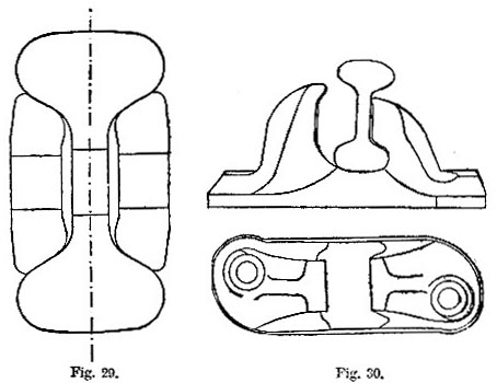
Fig. 29. Double-headed rail: New South Wales Railway.
Fig. 30. Chair, New South Wales Railway.
The sleepers are of colonial hard woods, chiefly iron-bark timber. They are laid 2 feet 6 inches apart between centres at the joints of the rails, and 3 feet 1 inch apart elsewhere. The upper and lower tables of the rails are curved or rounded in section to a radius of 5 1/4 inches, the height of the rail. The entering or overhanging faces of the rail are inclined at a slope of about 1 in 2, forming straight and equally inclined bearings to receive the fish-plates. The rails, while in course of manufacture, are tested by selecting a few rails of each day’s make, from which a portion 4 1/2 feet in length is cut off and placed on iron supports 3 1/2 feet apart, and is subjected to three blows from a weight of 1 ton falling 12 feet each time. The rails are to deflect not less than 6 1/2 inches and not more than 7 1/2 under this test without showing any signs of fracture. The fish-bolts, as well as the spikes for fastening the chairs to the sleepers, are made of the finest quality of close fibrous iron. Fifty per cent. of the rails were ordered 24 feet in length, 40 per cent. 21, and 10 per cent. 18. The chairs (fig. 30) are 13 1/2 inches long at the sole, 4 1/2 wide, and 1 1/2 thick at the seat of the rail. Test bars of the metal used for the chairs are cast to a scantling of 2 inches by 1 inch and 3 1/2 feet long. They are placed on edge, on supports 3 feet apart, and are required to sustain a dead load of 30 cwt. suspended from the centre of the bar without fracture. The spikes are seven-eights of an inch in diameter, tapered at the head to fifteen-sixteenths, with hemispherical or cup-heads forged from the solid bar. The above-described way, as laid in New South Wales, is bedded in ballast consisting of broken stone 12 inches in depth below the sleepers, broken to a gauge of 3 inches, boxed up with broken stone of a smaller size to a gauge of 2 inches for a depth of 8 inches. The total depth of the ballast from the crown of the formation is 22 inches. The surface of the formation below the ballast is rounded in cross-section, in order to drain off such water as penetrates through the ballast. Grips or furrows are cut and drains laid in where necessary, so that no water is allowed to remain on the line or under the ballast.
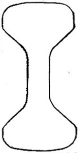
Fig. 31. Double-headed rail: South-Eastern Railway.
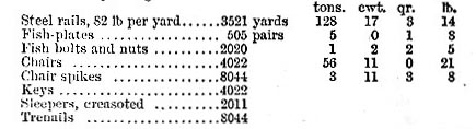
The South-Eastern double-headed rail (fig. 31) is keyed into chairs 4 1/2 inches wide and 13 7/8 long at the sole. They are fixed to the sleeper by two spikes driven into two hollow oak trenails. The sleepers at the joints are laid 2 feet 4 inches apart between centres. The following are the quantities of material for 1 mile of way, single line:—
These quantities are considerably less than those of the Midland Railway (which are stated below), as may naturally be the case for a line chiefly of passenger traffic in comparison with one of heavy goods and mineral traffic. The double-headed rails of the North-Eastern Railway, 82 lb per yard, are bedded on blocks or cushions of oak placed in the bottom of the chairs, the advantages of which have already been noticed.
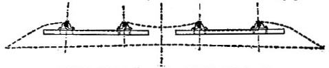
Fig. 32. Type section of way of Midland Railway.
Bull-Headed Rails
The type section of way of the Midland Railway is shown in fig. 32. The formation is inclined each way from the centre, making two straight slopes for drainage. The ballast is of strong gravel broken stone, and ashes or clinker,—chiefly gravel. It covers a width of 26 1/2 feet for two lines of way. It is laid to a depth of 16 inches at the middle of the six-foot, and is formed level with the upper sides of the sleepers between the rails in the four-foot, with a medium depth of 16 inches, or 11 inches beneath the sleepers. At the outer sides of the rails the ballast is heaped level with the tops of the chairs, or, more precisely, the tops of the keys, and is sloped down to the formation at each outer side.
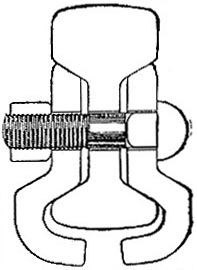
Fig. 33. Bull-headed rail and fishplate, Midland Railway.
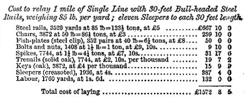
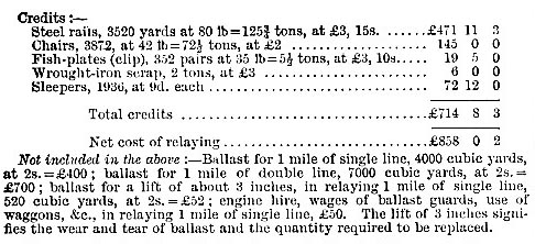
The upper and lower surfaces of the rail (see fig. 33) are curved to a radius equal to the height of it, and the planks are flat,—adapted for taking up lateral blows and mitigating wear. The chairs are remarkable for large dimensions, being 7 1/2 inches wide and 15 1/2 long at the sole, which is 1 7/8 inches thick under the rail, and for their weight, 50 lb each. The cost of relaying 1 mile of single way on the Midland system just described, based on contract prices in 1884, amounts to £1572, 8s. 5d. Deducting credit for old material to the amount of £714, 8s. 3d., the net cost of relaying is £858, 0s. 2d. The particulars of quantities, cost, and credit are given in the following statement, prepared by Mr. Alfred A. Langley, the engineer of the railway:—
The standard rail on the London and Northern-Western Railway is, like that of the Midland, bull-headed, but less high and wider at the head and the foot and thicker in the web. The chairs have the particularity of being ribbed horizontally on the inner face against which the oak key is driven, in order to grip the key. The sleepers at the joints are placed 2 feet 3 inches apart between centres. The Great Northern Company’s standard rail contrasts with the two immediately preceding rails in being less high than either, and having a thinner web and a larger head than the others. There are peculiarities in the disposition of the way. The first is that the joints of the rails are supported in a chair directly under each joint, to which the fishes are bolted; the second is that the two rails forming a line of way break joint with each other, the joints alternating from side to side, and that, as a consequence, all the sleepers are placed equally apart. On this system, it is argued, the way is of as nearly uniform strength as it is possible to make it. The keys for fixing the rails are of compressed fir. The Great Western, the Metropolitan, and the Lancashire and Yorkshire rails are the heaviest of the bull-headed rails noticed in Table XXVIII. (see below),—weighing 86 lb per yard, having comparatively thin webs and great development of head (see fig. 34). In the Great Western chair the inner face of the jaw that holds the key is formed with an indentation, to aid in keeping the key in place,—the key being likely to expand into the vacancy. In the Metropolitan way the chairs are fastened to the sleepers by two through bolts and nuts to each chair. The rails of the Manchester, Sheffield, and Lincolnshire Railway are placed in chairs of great length, 16 1/4 inches; and, contrary to usual practice, the oak keys for securing the rails in the chairs are fixed on the inner side of the rail, the rail taking its bearing directly upon the jaw of the chair. Thus the lateral strokes of the wheels on the rails are resisted directly by the jaw of the chair, and not through the medium of the key. There are twelve sleepers to each length of rail, averaging 2 feet 6 inches apart between centres, as against the usual number on other lines, eleven per rail-length of 30 feet. The sleepers, of Baltic redwood, are not creasoted nor preserved by any other process, except in one or two places where sand ballast is used.
The leading particulars of standard double-headed and bull-headed rails, with chairs and sleepers, are given in Table XXVIII. (see below).
Flange Rails
Specimen standard flange rails are illustrated in figs. 35 and 36 in cross section. Leading particulars of flange rails are given in Table XXIX below.
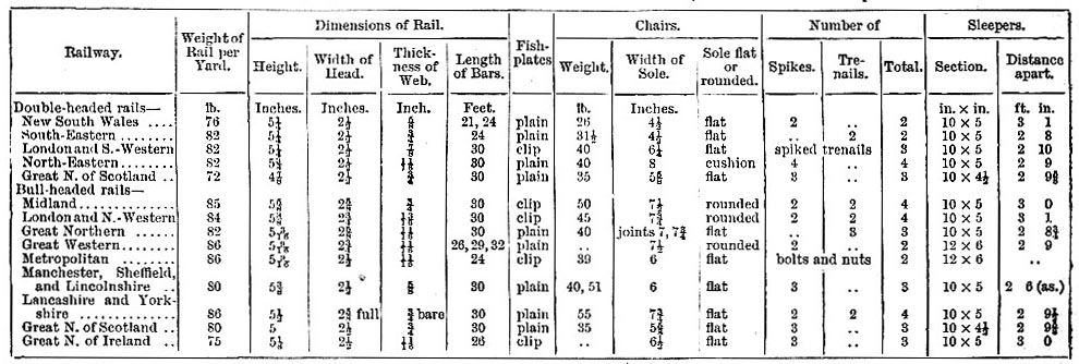
Table XXVIII. Standard Double-headed and Bull-headed Rails, with Chairs and Sleepers.
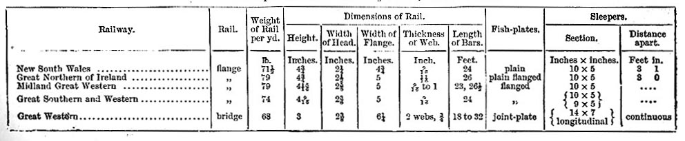
Table XXIX. Specimen Standard Gauge Rails - in Cross Section.
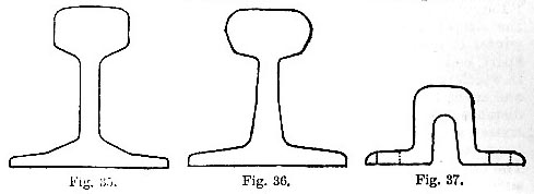
Fig. 35. Flange rail: New South Wales Railway.
Fig. 36. Flange rail: Midland Great Western Railway.
Fig. 37. Flange rail: Great Western Railway.
In the case of the flange rail of the New South Wales railway (fig. 35) the inward cant of the rails is provided for by planning out by machinery the beds of the rails at the upper sides of the sleepers to the angle 1 in 20; and that the rails may be kept in gauge the beds are notched into the surface by as much as the thickness of the flange of the rail. No holes of any kind, either punched or drilled, are made in the flanges of the rails; these are fastened to the sleepers by screws and spikes alternately, having projecting heads, by which the flange is clipped and held down. In order to check the tendency to creeping of the rails as well as of the fish-plates, it is intended to flange the fish-plates and to cut a notch at each end of them, in each of which a dog-spike is to be driven into the sleepers. The Great Northern of Ireland rail is similar to Mr. Fowler’s on the New South Wales Railway, but heavier. The Midland Great Western rail (fig. 36) is peculiarly formed, with a web of taper section, being nine-sixteenths of an inch thick at the head, and thickened to 1 inch at the flange. The bridge rail of the Great Western Railway (fig. 37) is laid on the model originally adopted by Mr. Brunel. The rails are only 3 inches high, and are aided in resisting vertical stress by the continuous longitudinal sleepers of large scantling, 14 inches wide and 7 deep, on which they are laid, with pine packing 8 inches wide and 1 thick. The rails are laid so as to break joint with the sleepers, which are lengths of 25 feet, whilst the rails are from 18 to 32 feet in length. The rails are fastened down by fang-bolts, which pass through their flanges and the sleepers together. At the joints they are fortified by square iron plates laid under the joints, through which fang-bolts are passed. The longitudinals are connected and kept to gauge by transoms or cross-ties at intervals.
The minimum weight of ordinary flange rails is about 45 lb per lineal yard. If the weight is less than this for main lines the upper bearing surface is objectionably narrow, and it is scarcely high enough above the sleepers. The maximum weight of flange rails is about 80 lb per lineal yard. Flange rails, like headed rails, are laid on transverse sleepers, to which they are fixed, most commonly by means of screws, spikes, or flange bolts and nuts. In all cases it is preferable to effect the fastening of steel rails without piercing them in the flange, as they are materially weakened by such perforations.
In the United States (also very largely in Germany, Canada, and Mexico) the Vignoles rail is universally used for railways, varying in weight from 67 or 70 lb per yard on a few leading lines to 30 lb on narrow-gauge railways. No railroads with any considerable traffic are now laid down with rails of less weight than 60 lb per yard. The Pennsylvania Railroad, laid to gauge of 4 feet 9 inches, is constructed of flange rails of two sections, one of 60 lb per yard 4 1/4 inches high, the other of 67 lb 4 1/2 inches high, in lengths of 30 feet. The fishes or splices are 2 feet in length, held by four bolts and nuts. The outer splice is formed with a horizontal flange or "tongue," which overhangs the flange of the rail and is spiked to the sleeper. Allowance for expansion when the rails are laid in winter is provided by laying the rails five-sixteenths of an inch apart, endwise; in summer a space of only one-sixteenths of an inch in width is allowed. The cross sleepers are 8 inches wide by 7 deep, and are 8 1/2 feet in length; they are laid so closely that the maximum distance apart between centres does not exceed 2 feet. There are sixteen sleepers for each length of 30 feet, and the sleepers at the joints are laid with a clearance of over 10 inches between them. The rails are fastened by spikes to the sleepers at the inside and the outside. The width for the double line of way at the formation level is 31 feet 4 inches in cuttings; and on embankments the width of the formations 24 feet 3 inches, sloping from the centre at the rate of 1 in 20. The ballast is laid to a depth of not less that 12 inches under the sleepers, and is filled in to the level of the upper surface of the sleepers. Where stone ballast is used it is broken uniformly to a gauge of 2 1/2 inches in diameter. For double lines of way large stones are placed in the bottom, at the centre, between the lines to provide for drainage; but the stones are not placed under the ends of the sleepers; thus water is drained off rapidly.
Read the rest of this article:
Railway, Railways - Table of Contents
|