1902 Encyclopedia > Railway, Railways (Railroad) > [Railway Carriages and Waggons] Continuous Brakes
Railway, Railways
(Part 40)
G. CARRIAGES AND WAGGONS (cont.)
Continuous Brakes
No department of railway practice has in recent years received closer attention and more minute study than that of continuous brakes,—brakes applied to the several vehicles in a train. With the amount of brake-power that had for many years been supplied to passenger trains—hand-brakes on tenders and guards’ vans—a train running at from 45 to 50 miles per hour on a straight level line could not be pulled up within from 800 to 1200 yards; and even that inadequate amount of brake-power was in the hands of several men. It was clear that the problem of arresting a train in the shortest distance could only be solved by bringing a power to bear on every part of the train in the shortest possible time. But the difficulty consisted in establishing continuity of action, so that the engine-driver or the guard should be enabled to apply the brake-blocks on a series of vehicles in one operation. Mechanical means were first tried, in the systems of Fay and Newall, in which the brakes are worked by a continuous rod passed under the vehicles. These systems were found to be available only on sections of not more than four or five vehicles, and were not worked by the driver but by the guard. In September 1858 a circular was issued by the Board of Trade to the railway companies, calling attention to the advantages to be derived from having their trains controlled by a sufficient amount of brake-power. Subsequently many inventions were tried,—brakes worked by fluid pressure, others worked by chains; but no practical solution of the problem appears to have been arrived at until Mr. Westinghouse of Pittsburgh, U.S.A., invented a really continuous brake worked by compressed air, which was quickly adopted in the United States, and was tried a few years later on several railways in England. It is still (1885) employed exclusively on the Metropolitan District Railway.
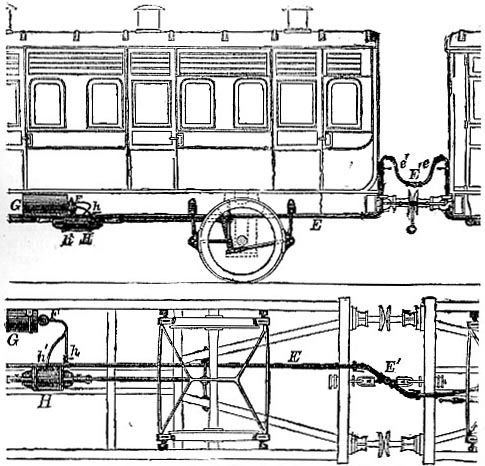
Fig. 44. E. the brake-pipe, extends the whole length of the train, connected between the vehicles by a coupling E', with flexible pipes e', e; F, the triple valve at the end of the reservoir G; H, the brake-cylinder, with pistons and rods connected with the brake-levers and the blocks suspended on frames; h, a branch pipe from the brake-pipe or main to the triple valve and reservoir; h', a branch pipe from the reservoir and triple valve to the brake cylinder.
Although the Westinghouse brake was greatly in advance of previously existing systems and answered ordinary requirements remarkably well, it became evident that for the worst types of accidents something more was wanted. The brake as first produced was non-automatic, being worked from the engine only, not by the guard. And, since the power had to travel from the engine along the whole length of the train, there was a loss of valuable seconds of time whilst the brake-blocks were being applied. Mr. Westinghouse therefore designed a system by which each vehicle was supplied with a complete brake apparatus, carrying its own store of power in the form of an auxiliary reservoir of compressed air, in addition to the brake cylinder already there. By the action of the "triple valve"—a later introduction—which is fitted to each smaller reservoir on the branch by which it is connected to the main or brake-pipe, the brakes can be instantly applied. A store of compressed air is maintained throughout the train in the continuous pipe and auxiliary reservoirs; and so long as the pressure in these is maintained the brakes are kept off. By a reduction of the pressure in the pipe the triple valve is brought into action, and the compressed air in the reservoir flows into the brake-cylinder and applies the brake. The brake can be at once released by restoring the pressure in the brake-pipe, when the compressed air in the cylinder escapes into the atmosphere. In the event of a train being parted and the brake-pipe severed, the escape of air reduces the pressure in the pipe, and the brakes are instantly self-applied. They have thus become known as "automatic" brakes. The compressed air by the agency of which the Westinghouse automatic brake is worked is stored in a main reservoir on the engine, as well as in the local reservoirs under the carriages, at a pressure of from 70 to 80 lb per square inch. The air is compressed by means of a steam-pump attached to the engine and worked by steam from the boiler. The compressed air is supplied through the brake-pipe, which passes through the whole length of the train to the secondary reservoirs. A brake-cylinder is fixed near each secondary reservoir, and the charge enters the cylinder at the middle of its length between the pistons, which are driven apart, one towards each end of the cylinder, and act, through piston-rods, and levers, upon the brake-blocks which are applied to the wheels. The pistons are maintained in their central positions in the brake-cylinder, when out of action, by spiral springs which abut on the ends of the cylinders; and so the brake-blocks are kept clear of the wheels. The general arrangement of the brake-apparatus applied to a carriage is shown in fig. 44; and the reservoir and brake-cylinder, with their connexions to each other and to the main pipe, and the intermediatary triple valve in section, are shown on a larger scale in fig. 45. The triple valve, by means of which instant automatic action throughout the train in produced, consists of a piston in a short cylinder, carrying a slide valve,—the piston and the valve moving together. A vehicle out of order can be cut out of the system by turning a tap, and brakes which have been applied by the parting of a train can be released by opening a valve on the cylinder.
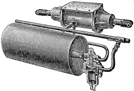
Fig. 45.
In 1874 a royal commission on railway accidents was appointed, and in June 1875 brake trials were made at Newark. On a level road a train, weighing 208·6 tons, running at a speed of 51 1/2 miles per hour, and fitted with the Westinghouse automatic pressure-brake—there tested for the first time on an English railway—was brought to a stand in a distance of 825 feet in the course of 18 seconds, —the equivalent distance for an initial speed of 50 miles per hour being 777 feet. In trials on the North-Eastern Railway in July 1879, a train, fitted with the Westinghouse brake, weighing 208 tons, and running at a speed of 51 miles per hour, was stopped in a distance of 621 feet in 14 3/4 seconds,—the equivalent distance for a speed of 50 miles per hour being 594 feet. In August 1877 the Board of Trade urged the railway companies to united and harmonious action, and stated the requirements which in their opinion were essential in a good continuous brake; it should be—efficient in stopping trains; instantaneous in action and easily applied by engine-drivers or guards; in case of accident instantaneously self-acting; capable of being put on or taken off with facility, on the engine, tender, and every vehicle of a train; regularly used in daily working; and the materials employed easily maintained and kept in order. That a brake should be instantaneous in action is evident on considering that at a speed of 50 miles per hour a train advances through 73 1/3 feet in a second of time. A striking example of the value of seconds under such circumstances is quoted in the Report, contrasting the working of the Westinghouse compressed-air brake and the Westinghouse vacuum-brake. The rates of speed were nearly the same,—about 52 miles per hour, or 76 feet per second. The train with the former brake ran 825 feet whilst that with the latter ran 1533 feet. Now, it took 7 3/4 seconds to put on the vacuum-brakes and 1 1/2 seconds to put on the pressure-brakes. The difference, 6 1/4 seconds, at 76 feet per second, makes a space of 475 feet traversed by the train before the brake came into action. In consequence of these steps taken by the Board of Trade all the large railway companies have now (1885) adopted continuous brakes, though some of these do not comply with the conditions of the Board of Trade. The principal question is not now that of automatic versus non-automatic, but of automatic pressure-brakes versus automatic vacuum-brakes. In the latter, as the name indicates, the work is done by the atmospheric pressure against the pressure of a comparative vacuum. At 31st December 1878 only 21 per cent. of the total carriage stock was fitted with brakes of some form, of which 12·8 per cent. were automatic; whilst at 30th June 1884 of the total carriage stock 76 per cent. was fitted with continuous brakes, of which 58 per cent. were automatic. It appears that there are in the United Kingdom considerably more Westinghouse automatic brakes in operation than any other single system. The same brake is very largely used in America and on the Continent, and at the end of 1884 it had been adopted to the extent of upwards of 15,000 sets for locomotives and 78,000 for carriages.
Read the rest of this article:
Railway, Railways - Table of Contents
|