1902 Encyclopedia > Aqueduct > Loch Katrine Aqueduct, Glasgow, Scotland
Aqueduct
(Part 13)
Loch Katrine Aqueduct, Glasgow, Scotland
The Loch Katrine Aqueduct of the Glasgow Waterworks is the modern aqueduct which has most probably attracted the largest share of public attention.
The appropriate of the beautiful waters of Loch Katrine -- renderd classical by Sir Walter Scott -- the romantic, rugged, and almost impassable Highland country through which the aqueduct had to be constructed, and the distance from Lock Katrine to Glasgow, all contributed to lend a special interest to the undertaking. It is, however, a very simple work in itself, for, with but little artificial addition, Loch Katrine, Loch Venachar, and Loch Drunkie were converted into impounding reservoirs, the first for the supply of the city, and the two latter for compensation.
The area and capacity of these reservoirs are as follows:--
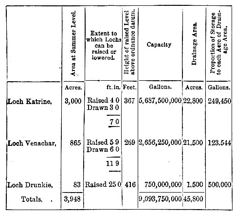
The length of the aqueduct from Loch Katrine to Glasgow is about 35 miles, of which 27 may be considered as the aqueduct proper. The reamining 8 consist of two lines of cast-iron pipes, by which the water is conveyed from the large service reservoir at Mugdock to the city of Glasgow. The aqueduct is principally in tunnel or covered conduit, but there are three valleys which are crossed by iron siphon pipes of large diameter, and there are numerous aqueduct bridges of varied character, suited to the peculiarities of the districts in which they had to be constructed. The tunnels and covered conduits are 8 feet high and 8feet wide, with an inclination of 10 inches in a mile, a are capable of conveying about 50,000,000 gallons of water in twenty-four hours. The siphon pipes across the valleys have an inclination of 1 in 1000, or about 5 feet in a mile, and it requires two pipes of 4 feet in diameter and one of 3 feet in diameter, to convey the quantity of water in a day which the aqueduct will deliver.
The work required the greatest engineering accuracy and skill, and so perfectly have the lines and levels been kept, that it was only upon the closest examination that the joinings in the tunnels could be detected.
The work was commenced in the spring of 1855, opened by her Majesty the Queen in October 1859, and finally completed in the course of 1860.
The cost of the engineering works of the aqueduct, including the conversion of the various lochs mentioned into reservoirs, and exclusive of land, and of the distribution of the water in the city of Glasgow and its neighbourhood, was 668,000 pounds; but the gross cost of the water supply, including the purchase of two water companies, distribution, and everything, has been, to May 1873, £1,756,793.
The following description of the aqueduct was given by the engineer at a banquet given to him in Glasgow after the completion of the works:-
"It is impossible to convey to those who have not personally inspected it, an impression of the intricacy of the wild and beautiful district through which the aqueduct passes for the first 10 or 11 miles after leaving Loch Katrine. From the narrowest point at which it was found the ridge between Loch Katrine and Loch Chon could be pierced, the country consists of successive ridges of the most obdurate rock, separated by deep wild valleys, in which it was very difficult in the first instance to find a way. There were no roads, no houses, no building materials,-nothing which would ordinarily be considered essential to the successful completion of a great engineering work for the conveyance of water; but it was a consideration of the geological character of the material, which gave all the romantic wildness to the district, that at once determined me to adopt that particular mode of construction which has been so successfully carried out. For the first 10 miles , the rock consists of mica schist and clay slate-close, retentive material, into which no water percolates, and in which, consequently, few springs are to be found. This rock, when quarried, was unfit for building purposes; there was no stone of a suitable description to be had at any reasonable cost or distance, no lime for mortar, no clay for puddle, and no roads to convey material. Ordinary surface construction, therefore, was out of the question; but I saw that if tunneling were boldly resorted to, there would be no difficulty, beyond the cost and time required in blasting the rocks, in making a perfectly water-tight and all-enduring aqueduct; there would be no water to hamper and delay us in the shafts and tunnels, and little would require transporting through the country but gunpowder and drill iron. This course was therefore determined upon, and my expectations have been realized to the very letter. The aqueduct may be considered as one continuous tunnel. As long as the work continued in the primary geological measures, we had no water; and even after it entered the Old Red Sandstone, and where it subsequently passed through trap rock, there was much less than I expected; so that our progress; at no part of the work, was ever materially interfered with by those incidents which usually render mining operations costly and uncertain."
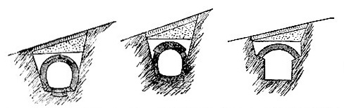
(From left to right)
Fig. 6 -- Open cutting not water-tight
Fig. 7 -- Open cutting water-tight, but lined
Fig. 8 -- Open cutting in rock
(From left to right)
Fig. 9 -- Aqueduct above surface of ground
Fig. 10 -- Tunnel lined
Fig. 11 -- Tunnel through water-tight rock
The rock, however, especially the mica slate, proved extremely hard and difficult to work. At several points along the side of Loch Chon the progress did not exceed 3 or 4 lineal yards in a month at each face, although the work was carried on day and night. The average progress through the mica slate was about 5 yards in a month. In drilling the holes for blasting, a fresh drill was required for every inch in depth on the average, and about sixty drills were constantly in use at each face. The cost of the gunpowder alone, consumed in the first 7 1/2 miles of the aqueduct, was £10,540, and there were about 175 miles of fuse burned in firing it. The average cost per yard of this length of the aqueduct was over £13, or £23,000 per mile. (Figs. 6 to 11 are cross sections of the aqueduct, showing the general construction in various kinds of ground.) The built and tunneled part is all capable of passing 50,000,000 galloons per day.-
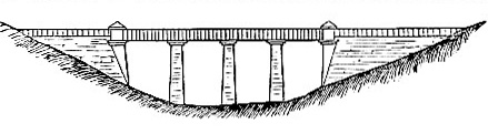
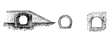
Fig. 12 -- Iron Aqueducts at Culegarton
The aqueduct bridges over the ravines are somewhat peculiar, varying in character according to the circumstances of the district. In the wilder and more inaccessible parts there are five extensive iron ones, varying in length from 124 to 332 yards, all of similar construction. (See Fig. 12). At the ends of these bridges, in the shallowest parts of the ravines, the aqueduct has a cast-iron trough supported on a solid dry stone embankment of the stone of the district, carefully set by hand; the stone embankment being 9 feet wide at top, with a batter of 3 inches to the foot on each side. The deeper parts of the ravines or valleys are crossed by malleable iron tubes 8 feet wide by 6 1/2 feet high inside, supported by piers at intervals of 50 feet. The bottoms and sides of these tubes are 3/8 inch thick, and the tops 7/16 inch thick, strengthened by angle and T iron. Fig. 13 shows a section of these tubes. The cast-iron made for adding 2 1/2 feet to the height of the sides when additional water was required, and this since been done. The bottoms of the malleable-iron tubes are 3 feet below the bottoms of the troughs, so that they should always be full of water, for the purpose of securing the same temperature both in the bottom and top of the tubes, and so preventing unequal expansion and contraction. The aqueduct at the crossing of small mountain-streams (of which there were many) was carried in cast-iron troughs similar to those already described, supported upon cast-iron beams over the space left for the stream.
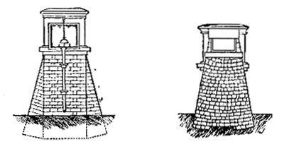
Fig. 13 -- Section through Iron Tube
Fig. 14 -- Section through Cast-iron Trough
The first deep valley which required to be crossed by piping is that of the Duchray water, about 55 chains wide. The pipes first laid down were 4 feet diameter in 9 feet lengths, with spigot and faucet joints, run up with lead in the usual way. At the lowest point pipes are under a pressure of 165 feet. The river itself is crossed by cast-iron arched girders of 60 feet span; and here, as well as at the small basins at each end of the piping, and at all other places where masonry was required, provision was made for laying two additional lines of pipes, one 4 feet and the other 3 feet in diameter. These pipes have since been laid. After passing through the ridge of Old Red Sandstone conglomerate by the Clashmore tunnels, the aqueduct for 5 miles is for the greater part in open cutting, with masonry sides, and a dry rubble arch covered with 2 feet of puddle, and then covered in.
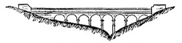
Fig. 15 -- Duntreath Aqueduct
The Endrick valley, like that of the Duchray, is crossed by cast-iron siphon pipes for 2 1/4 miles in length. Where they cross the river Endrick at the bottom of the valley, the pipes are 1 5/8 inches thick, and have to sustain a pressure of 235 feet. The pipes are carried across small depressions in the valley by resting them upon stone piers, and at the crossing of two roads, and of the Forth and Clyde railway, they are further supported by cast-iron troughs (fig. 14) are 8 feet broad and 4 feet deep, and 5/8 inch thick, and were capable of passing at this depth upwards of 20,000,000 gallons a day. Provision was brackets. The pipes at these exposed places have flange joints, and they have been covered with woolen felt to prevent expansion and contraction. There is a short tunnel 110 yards long on this length of piping of dimensions sufficient to carry the three-lines of pipes. The construction of the aqueduct, for the5 miles extending from the valley of the Endrick to the valley of the Blane, presents the same general features as those already described. Good building stone was abundant in this district, and the bridges are all of masonry. Fig. 15 is an elevation of one of the aqueduct bridges near Killearn at 19 miles from Loch Katrine, and figs. 16 and 17 are details of the Ballewan Aqudeuct bridge (fig. 18.)
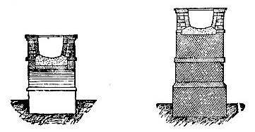
Fig. 16 -- Section through Arch
Fig. 17 -- Section through Pier
The piping across the Blane is about 54 chains long, with a depression of 125 feet. The Blame water itself is crossed by a stone bridge, and there are basins at each end of the pipes as before. The last piece of the aqueduct is a tunnel 2640 yards long, through a ridge of amydaloidal trap, separating the valley of the Blane from the valley of the Alladner. The tunnel is 250 feet below the summit of the hill.
Mr. Bateman, at the banquet referred to, summarized the works along the line of aqueduct in nearly the following words:--
"There are in whole work eighty distinct tunnels, upon which forty-four vertical shafts have been sunk for facilitating and expediting the completion of the work." Besides the tunnel at the commencement of the aqueduct, called the Loch Katrine Tunnel, 2325 yards in length, and upwards of 500 feet below the summit of the hill, and the Mugdock Tunnel at the end of the aqueduct, 2640 yards in length, there are "others, 700, 800, 1100, and 1400 yards in length. Not to speak of smaller constructions, there are twenty-five importation iron and masonry aqueducts over rivers and ravines, some 60 and 80 feet in height, with arches of 30 feet, 50, and 90 feet in span. The number of people employed, exclusive of iron-founders. And mechanics, has generally been about 3000; and for the greater part of these, huts and roads and all other accommodation had to be provided, the country for the most part being of the wildest and most inaccessible description." -- . . . . . "At the picturesque, ‘turf and timber’ village of Sebastopol, as the miners called it, at the head of Loch chon, several hundreds of workpeople were accommodated. Provision stores, reading-rooms, a school-house and church, and a resident medical man and school-master were provided for them."
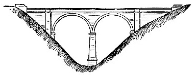
Fig. 18 -- Ballewan Aqueduct
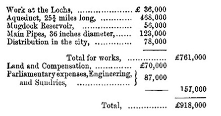
The aqueduct from its commencement at Loch Katrine to the Mugdock reservoir is 25 3/4 miles long, 13 of which were tunneled, 3 3/4 miles are iron piping across valleys, and the remaining 9 miles consist of "cut and cover" conduit and bridges. Where the ground was cut open the conduit was covered it. At the bridges the aqueduct is covered with timber to prevent its being choked by snow. Most of them are furnished with grooves in the masonry to receive stop planks, and with discharge sluices to facilitate the emptying of the aqueduct, when it is necessary to inspect or make repairs. Overflows are constructed at a number of the bridges, to discharge the water if it should be necessary to stop the flow suddenly any point. The total cost of the aqueduct at the time the water was introduced into the city was £468,000, or an average of £18,000 per mile.
It has been already stated that the 4-feet pipes across the valleys on the line of aqueduct were intended to deliver 20,000,000 gallons a day. By the well-known modification of Eytelwein’s formula, deduced from Du Baut’s experiments and more elaborate formulae, the computed discharge is 21,5000,000 gallons a day nearly, and by Weisbach’s formulae, 21,750,000 gallons a day. These pipes, however, have discharged 24,000,000 gallons a day without their being completely gorged, and their ultimate discharge has therefore yet to be determined. The whole of the pipes used in the works were coated with coal pitch and oil, according to the process patented by Dr. R. A. Smith of Manchester, and first used by Mr. Bateman in the Manchester Waterworks. This coating, when well done, imparts a smooth glassy surface to the pipes, and prevents, at least for a number of years, the usual, and it may be said, inevitable oxidation. Weisbach found that for wooden pipes 2 1/2 and 4 1/2 inches diameter, the coefficient of resistance was 1.75 times as great as for "metallic pipes," giving a discharge about 14 per cent less: and M. Morin has shown, in a paper which it is believed is published in detail in the Mémoires des Savants Etrangers, the influence the state of the surface has upon the discharge of a pipes amounting, in cast-iron pipes coated with pitch, and in glass pipes, to an increase of nearly one-third in the discharge.
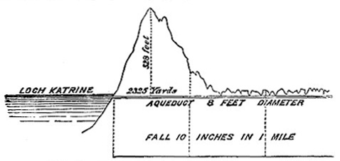
Fig. 19 -- Part Section of Loch Katrine Aqueduct
It has also been pointed out by M. Morin, whose deductions are principally from observations by M. Darcy, director of the waterworks of Paris, that for large sizes the diameters of the pipes seem also to exercise a more decided influence on the discharge than has been hitherto assigned to them. Late observations on the flow of gas through pipes by M. Arson, engineer of the Paris gas Company, tend to confirm the views of M. Morin.
At the Mugdock Service reservoir, 7 or 8 miles from Glasgow, the water is first discharged into a basin, from which it passes over cast-iron gauge plates, 40 feet wide, brought to a thin edge. The depth of water passing over these plates is regularly recorded and the discharge computed. From the basin the water falls into an upper division of the main reservoir, about 2 acres in extent, and from this it is discharged into the rservoir. The reservoir has a water surface of 60 acres, and a depth when full of 50 feet; it contains 548,000,000 gallons, and is 317 feet above ordnance datum. It admits of repair being made upon the aqueduct without interrupting the supply of water to the city. Two earthen embankments were necessary to form the reservoir; the main embankment is 400 yards long and 68 feet high, and the easterly embankment 240 yards long and 50 feet high, each with a puddle wall in the centre, and pitching on the front slope in the usual way.
The water is drawn from the reservoir by pipes laid in a tunnel through the hill between the two embankments, there being no pipes through the embankments themselves.
At the end next the reservoir there is a stand-pipe so arranged that water can be drawn at various heights, and about 50 yards from the reservoir, the water passes into a circular well cut out of the rock, 40 feet in diameter and 63 feet deep, and is strained by passing through copper wire-cloth, 40 meshes to the inch, arranged in oak frames, forming an inner well of octagonal shape 25 feet diameter; and from this latter the water finally passes into the two lines of pipes leading to the city. Water can also be drawn direct from the gauge basin, and from the upper compartment of the reservoir into the straining well, by a line of 4 feet pipes through the bottom of the reservoir. These works, including road and stream diversions, cost about £56,000.
The two pipes leading from the straining well are each 42 inches diameter, and intended to deliver the whole 50,000,000 gallons a day; but on emerging from the tunnel, which is 440 yards in length, they are diminished to 36 inches, and they are continued of this size to the city. Provision was made for additional pipes, which have since been laid. The different lines of pipes are laid side by side for about 3 miles, after which they diverge -- one line being carried by the Great Western Road for the supply of the low districts of the city, and the other by Maryhill for the supply of the high districts. These pipes come together again, and are arranged so as to communicate when necessary at St. Goerge’s Road near the commencement of the city, up to which point their respective lengths from the straining well are 7 miles for the low district main, and 6 x miles for the high. Each of these lines of pipes crosses the River Kelvin and the Forth and Clyde canal, and at these places provision was made of additional pipes. Eleven feet were added to the width of the Kelvin Bridge on the Great Western Road, by cast-iron girders, to carry the low district mains. The tow middle spans are each 93 feet, and the two side arches 37 feet span.
The total cost of the works at their completion, in 1860, was as follows:--
|