1902 Encyclopedia > Railway, Railways (Railroad) > Kinds of Rail
Railway, Railways
(Part 3)
A. RAILWAYS - HISTORY (cont.)
Kinds of Rail
Meantime the construction of the way was the subject of much consideration. The fish-belly form of wrought-iron rail was troublesome to roll, and so the flat-bottom or flat-foot rail (fig. 4) was designed, combining a solid head with a flange base.
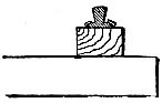
Fig. 4. The flat-bottomed rail.
This rail, with holes through the flange to hold the spikes, was used to some extent, and was laid on longitudinal timber sleepers, and also on transverse sleepers. The disadvantage was want of vertical stiffness of the system; and, if the rail was made higher, it was liable to rock on the sleeper and work loose on the spikes. This rail, known as the Vignoles rail, has been much improved in form and proportions and is extensively used.
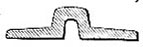
Fig. 5. The bridge rail.
The bridge rail (fig. 5)—so called because it was first laid on bridges—was that first used on the Great Western Railway, and is of a shallow section, but wide, and possessed of lateral stiffness. The first line was a series of beech piles, 12 inches square. Driven into the ground, to which were bolted at the surface level cross balks of timber, one on each side of the pilehead on which they were shouldered. Longitudinal balks, 15 feet long, were laid on the cross balks. The longitudinal were covered with oak or elm planking screwed down to the surface. When the ballast was packed under the longitudinal balks, the surface of the oak planks was planed level, and the bridge rails screwed down on them, with felt between. It was supposed that there would be no yielding whatever, but a very short time demonstrated that the piles formed a series of solid resistances, while the balks between sprang, and it was found necessary to cut away the piles. Transoms were then framed into the longitudinals and secured by strap-bolts, and the whole resembled a long ladder laid on the ground. Eight different sections of rails were tried in succession; one section measured 1 1/2 inches in height by 7 inches in width, weighing 44 lb. per yard; and the last section 2 3/4 inches high by 6 inches wide, weighing 62 lb. per yard.
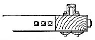
Fig. 6. Bridge rail on the Great Western Railway.
The screws which held down the rails were counter-sunk beneath the wheel-flanges, and nut-headed on the other side (see fig. 6). In consequence of the want of depth in the rails, they bent longitudinal under the wheels, and the horizontal flanges curled up at the sides, while the holes through them bent into angles. One remedy tried was to cross-board the longitudinal timbers on the surface, and thus the fibre was made less yielding.
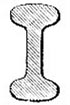
Fig. 7. The double-headed rail.
The double-heated rail (fig. 7) was originated by Joseph Locke, and was first laid on the Grand Junction Railway. It also weighed 62 lb. per yard. The two tables were equal; the rail was more easily rolled than others, and, being reversible, it was in fact two rails in one. But as it was laid in cast-iron chairs the lower table was exposed to damage under the hammering of the traffic; and many engineers were led to make the lower table of smaller size, as in fig. 8, merely as a support, not as a surface to be used by the wheels.
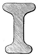
Fig. 8. The bull-headed rail (62 lb. per yard).
This rail, which acquired the title of "bull-headed," was, like the flat-foot and bridge rails, used as a prop supported on its base. There was a waste of metal in these early rails, both flat-foot and double-headed, owing to the excessive thickness of the vertical web, which has been corrected in recent designs. It was found, naturally, that rails would not rest in their chairs at the joints, but were loosened and bruised at the ends by the blows of the traffic. The fish-joint was therefore devised in 1847 by Mr. W. Bridges Adams, the intention being by "fishing" the joints to convert the rails into continuous beams.
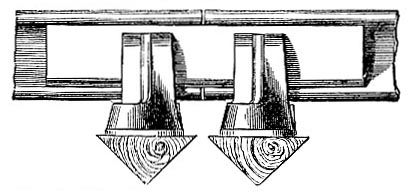
Fig. 9. The original fish-joint, W. Bridges Adams.
In the original design two chairs were placed, one under each rail, a few inches apart, as in fig. 9. The joint was thus suspended between the two chairs, and two keys of iron, called "fishes," fitting the side channels of the rails, were driven in on each side between the chairs and the rails. In subsequent modification the fishes were, and they continue to be, bolted to and through the rails, the sleepers being placed further apart, and the joint suspended between them.
Read the rest of this article:
Railway, Railways - Table of Contents
|